One transistor, four resistors, two capacitors: the 1968 EHX LPB-1
circuit-analysis
history
Published
July 29, 2026
Every pedal on your board is built from gain stages. A Big Muff chains four of them. A Tube Screamer folds one around an op-amp. Whatever gets dissected on this site later will decompose into this one building block, so the first article is about the atom.
The specimen: the Electro-Harmonix LPB-1 Linear Power Booster, EHX’s first product, sold by mail order from 1968 [1], [2]. It is a single gain stage and nothing else — one transistor, four resistors, two capacitors. By the end of this article you will know what each part is for, and you will have watched the stage do the two things every gain stage does: amplify, and clip.
Gain
A gain stage takes a voltage signal and outputs a larger copy. A guitar pickup delivers somewhere between 50 and 200 mV. For the circuit below, the size of the copy is set — to a first approximation — by two resistors:
A_v \;\approx\; -\,\frac{R_C}{R_E}
Two things to notice. The formula does not contain the transistor: the gain is set by parts costing a rappen each. That is almost true, and the error will be visible in the simulation below. Second, the minus sign — the output is inverted. For a single stage this is inaudible; the ear does not register absolute polarity. It starts to matter when stages are chained, which is a later article.
Decibels, since they come up constantly here: A_{dB} = 20\log_{10}|A_v|. A gain of 25 is about 28 dB.
The circuit
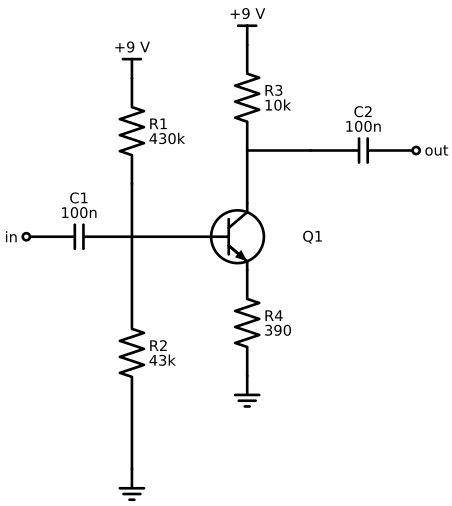
Component values are from traced vintage units [3], [4]; the current reissue matches [5].
Code
import schemdrawimport schemdraw.elements as elmwith schemdraw.Drawing() as d: d.config(unit=2.2, fontsize=11) Q = elm.BjtNpn(circle=True).anchor('base').label('Q1', 'right', ofst=.8)# input side: a short lead first, so the divider tap sits# clearly left of the transistor elm.Line().at(Q.base).left(d.unit*0.75) tap = d.here elm.Capacitor().left().label('C1\n100n', 'top').reverse() elm.Dot(open=True).label('in', 'left')# bias divider, now on its own vertical line elm.Line().at(tap).up(d.unit*0.5) elm.Resistor().up().label('R1\n430k', 'bottom') elm.Vdd().label('+9 V') elm.Resistor().at(tap).down(d.unit*2.2).label('R2\n43k', 'bottom') elm.Ground()# collector side: rise first, then branch — R3 continues up,# C2 taps the junction and exits right, clear of the transistor elm.Line().at(Q.collector).up(d.unit*0.5) junc = d.here elm.Resistor().up().label('R3\n10k', 'bottom') elm.Vdd().label('+9 V') elm.Line().at(junc).right(d.unit*0.6) elm.Capacitor().right().label('C2\n100n', 'top') elm.Dot(open=True).label('out', 'right')# emitter side unchanged elm.Resistor().at(Q.emitter).down().label('R4\n390', 'bottom') elm.Ground()
Figure 1: The LPB-1 gain stage. One NPN transistor in common-emitter configuration; component values from the 1968 original.
Signal path, left to right. C1 passes the signal and blocks DC — the base must sit at a fixed resting voltage, and the guitar is not invited to disturb it. R1 and R2 divide the 9 V supply down to about 0.82 V at the base, which sets roughly 0.5 mA of collector current, which drops the collector to about 4.1 V — near half the supply, leaving close to maximum room to swing in both directions. Wiggle the base and the collector current follows; R3 converts that current wiggle back into a voltage, larger than the input by the resistor ratio:
C2 passes the amplified signal out and keeps the 4.1 V to itself.
NoteWhere it came from
Mike Matthews founded EHX in 1968 with $1,000; the LPB-1 came out of prototype work with Bob Myer, an engineer at Bell Labs [2], [6]. The original transistor was a 2N5133; the simulation below uses the better-documented 2N5088 — the same substitution EHX themselves made later [5]. Whether that substitution is audible is a question for its own article.
Simulation
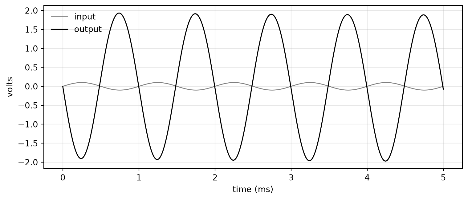
Claims require receipts. The netlist sits next to this article as spice/lpb1.cir; run it yourself with ngspice -b. Input: a 100 mV, 1 kHz sine — guitar-scale.
The five lines that run ngspice and read its answer
import subprocess, tempfile, pathlibimport pandas as pdNETLIST = pathlib.Path("spice/lpb1.cir").read_text()def run_stage(amplitude_v=0.1):"""Run the LPB-1 deck with a given input amplitude; return a DataFrame.""" deck = NETLIST.replace("SIN(0 0.1 1k)", f"SIN(0 {amplitude_v} 1k)")with tempfile.TemporaryDirectory() as tmp: deckfile = pathlib.Path(tmp) /"deck.cir" deckfile.write_text(deck) subprocess.run(["ngspice", "-b", deckfile.name], cwd=tmp, check=True, capture_output=True) df = pd.read_csv(pathlib.Path(tmp) /"waves.dat", sep=r"\s+", names=["t", "vin", "t2", "vout"])return df[["t", "vin", "vout"]]
Figure 2: 100 mV in (grey), roughly 2.2 V out (black). The stage delivers a gain of about 22 — and note the output is upside down, exactly as the minus sign promised.
In: 100 mV. Out: 2.2 V, upside down. Gain of 22.
The formula said 26. The missing part is the transistor’s internal emitter resistance — about 50 Ω at this operating point — which adds to R4. SPICE includes it; the napkin does not [7, Ch. 2]. That term, and why it makes gain drift with bias and temperature, is a future article.
Clipping
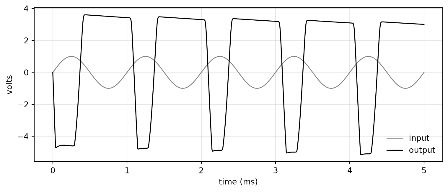
The collector can swing between the supply rail and slightly above ground: about 8.5 V of room. Feed the stage 1 V and it would need 22 V of output. It does this instead:
Figure 3: The same stage fed 1 V. The output flattens against both rails — asymmetrically, note the tops differ from the bottoms. This waveform is the founding document of the fuzz industry.
The tops and bottoms are cut off, and unevenly — the stage runs out of room downward before upward. A flattened waveform contains harmonics that were not in the string’s motion; that is what “breakup” is. The asymmetry decides which harmonics, and a good share of pedal design consists of shaping exactly that.
Distortion is a gain stage pushed past politeness. Most circuits this site will ever analyze are variations on the two plots above: where the ceiling sits, how hard the signal hits it, and what shape the clipping takes.
Skipped, deliberately
Bias stability. What C1 and C2 do to the low end. Input and output impedance, and why the pickup cares about them. The internal resistance behind the 22-versus-26 gap. Each gets its own article; this one only needed the atom.
Netlist, schematic code, and page source are in the site repository. Run the deck, bend the values, argue with the results.
P. Horowitz and W. Hill, The art of electronics, 3rd ed. Cambridge University Press, 2015.
Source Code
---title: "What is a gain stage?"subtitle: "One transistor, four resistors, two capacitors: the 1968 EHX LPB-1"date: 2026-07-29categories: [circuit-analysis, history]code-fold: truedraft: false---Every pedal on your board is built from gain stages. A Big Muff chains fourof them. A Tube Screamer folds one around an op-amp. Whatever gets dissectedon this site later will decompose into this one building block, so the firstarticle is about the atom.The specimen: the Electro-Harmonix LPB-1 Linear Power Booster, EHX's firstproduct, sold by mail order from 1968 [@ehx-flashback; @musicradar-matthews].It is a single gain stage and nothing else — one transistor, four resistors,two capacitors. By the end of this article you will know what each part isfor, and you will have watched the stage do the two things every gain stagedoes: amplify, and clip.## GainA gain stage takes a voltage signal and outputs a larger copy. A guitarpickup delivers somewhere between 50 and 200 mV. For the circuit below, thesize of the copy is set — to a first approximation — by two resistors:$$A_v \;\approx\; -\,\frac{R_C}{R_E}$$Two things to notice. The formula does not contain the transistor: the gainis set by parts costing a rappen each. That is *almost* true, and the errorwill be visible in the simulation below. Second, the minus sign — the outputis inverted. For a single stage this is inaudible; the ear does not registerabsolute polarity. It starts to matter when stages are chained, which is alater article.Decibels, since they come up constantly here: $A_{dB} = 20\log_{10}|A_v|$.A gain of 25 is about 28 dB.## The circuitComponent values are from traced vintage units [@beavis-lpb1; @tgmusic-lpb1];the current reissue matches [@coda-lpb1].```{python}#| label: fig-schematic#| fig-cap: "The LPB-1 gain stage. One NPN transistor in common-emitter configuration; component values from the 1968 original."import schemdrawimport schemdraw.elements as elmwith schemdraw.Drawing() as d: d.config(unit=2.2, fontsize=11) Q = elm.BjtNpn(circle=True).anchor('base').label('Q1', 'right', ofst=.8)# input side: a short lead first, so the divider tap sits# clearly left of the transistor elm.Line().at(Q.base).left(d.unit*0.75) tap = d.here elm.Capacitor().left().label('C1\n100n', 'top').reverse() elm.Dot(open=True).label('in', 'left')# bias divider, now on its own vertical line elm.Line().at(tap).up(d.unit*0.5) elm.Resistor().up().label('R1\n430k', 'bottom') elm.Vdd().label('+9 V') elm.Resistor().at(tap).down(d.unit*2.2).label('R2\n43k', 'bottom') elm.Ground()# collector side: rise first, then branch — R3 continues up,# C2 taps the junction and exits right, clear of the transistor elm.Line().at(Q.collector).up(d.unit*0.5) junc = d.here elm.Resistor().up().label('R3\n10k', 'bottom') elm.Vdd().label('+9 V') elm.Line().at(junc).right(d.unit*0.6) elm.Capacitor().right().label('C2\n100n', 'top') elm.Dot(open=True).label('out', 'right')# emitter side unchanged elm.Resistor().at(Q.emitter).down().label('R4\n390', 'bottom') elm.Ground()```Signal path, left to right. **C1** passes the signal and blocks DC — thebase must sit at a fixed resting voltage, and the guitar is not invited todisturb it. **R1** and **R2** divide the 9 V supply down to about 0.82 V atthe base, which sets roughly 0.5 mA of collector current, which drops thecollector to about 4.1 V — near half the supply, leaving close to maximumroom to swing in both directions. Wiggle the base and the collector currentfollows; **R3** converts that current wiggle back into a voltage, largerthan the input by the resistor ratio:$$A_v \approx -\frac{R_3}{R_4} = -\frac{10\,\text{k}\Omega}{390\,\Omega}\approx -26$$**C2** passes the amplified signal out and keeps the 4.1 V to itself.::: {.callout-note}## Where it came fromMike Matthews founded EHX in 1968 with \$1,000; the LPB-1 came out ofprototype work with Bob Myer, an engineer at Bell Labs[@ehx-story; @musicradar-matthews]. The original transistor was a 2N5133;the simulation below uses the better-documented 2N5088 — the samesubstitution EHX themselves made later [@coda-lpb1]. Whether thatsubstitution is audible is a question for its own article.:::## SimulationClaims require receipts. The netlist sits next to this article as[`spice/lpb1.cir`](spice/lpb1.cir); run it yourself with `ngspice -b`.Input: a 100 mV, 1 kHz sine — guitar-scale.```{python}#| label: run-helper#| code-summary: "The five lines that run ngspice and read its answer"import subprocess, tempfile, pathlibimport pandas as pdNETLIST = pathlib.Path("spice/lpb1.cir").read_text()def run_stage(amplitude_v=0.1):"""Run the LPB-1 deck with a given input amplitude; return a DataFrame.""" deck = NETLIST.replace("SIN(0 0.1 1k)", f"SIN(0 {amplitude_v} 1k)")with tempfile.TemporaryDirectory() as tmp: deckfile = pathlib.Path(tmp) /"deck.cir" deckfile.write_text(deck) subprocess.run(["ngspice", "-b", deckfile.name], cwd=tmp, check=True, capture_output=True) df = pd.read_csv(pathlib.Path(tmp) /"waves.dat", sep=r"\s+", names=["t", "vin", "t2", "vout"])return df[["t", "vin", "vout"]]``````{python}#| label: fig-clean#| fig-cap: "100 mV in (grey), roughly 2.2 V out (black). The stage delivers a gain of about 22 — and note the output is upside down, exactly as the minus sign promised."import matplotlib.pyplot as pltdf = run_stage(0.1)fig, ax = plt.subplots(figsize=(8, 3.5))ax.plot(df.t *1e3, df.vin, color="grey", lw=1, label="input")ax.plot(df.t *1e3, df.vout, color="black", lw=1.2, label="output")ax.set_xlabel("time (ms)"); ax.set_ylabel("volts")ax.legend(frameon=False); ax.grid(alpha=.3)plt.tight_layout()```In: 100 mV. Out: 2.2 V, upside down. Gain of 22.The formula said 26. The missing part is the transistor's internal emitterresistance — about 50 Ω at this operating point — which adds to R4. SPICEincludes it; the napkin does not [@horowitz-hill, ch. 2]. That term, and whyit makes gain drift with bias and temperature, is a future article.## ClippingThe collector can swing between the supply rail and slightly above ground:about 8.5 V of room. Feed the stage 1 V and it would need 22 V of output.It does this instead:```{python}#| label: fig-clipped#| fig-cap: "The same stage fed 1 V. The output flattens against both rails — asymmetrically, note the tops differ from the bottoms. This waveform is the founding document of the fuzz industry."df = run_stage(1.0)fig, ax = plt.subplots(figsize=(8, 3.5))ax.plot(df.t *1e3, df.vin, color="grey", lw=1, label="input")ax.plot(df.t *1e3, df.vout, color="black", lw=1.2, label="output")ax.set_xlabel("time (ms)"); ax.set_ylabel("volts")ax.legend(frameon=False); ax.grid(alpha=.3)plt.tight_layout()```The tops and bottoms are cut off, and unevenly — the stage runs out of roomdownward before upward. A flattened waveform contains harmonics that werenot in the string's motion; that is what "breakup" is. The asymmetry decideswhich harmonics, and a good share of pedal design consists of shapingexactly that.Distortion is a gain stage pushed past politeness. Most circuits this sitewill ever analyze are variations on the two plots above: where the ceilingsits, how hard the signal hits it, and what shape the clipping takes.## Skipped, deliberatelyBias stability. What C1 and C2 do to the low end. Input and outputimpedance, and why the pickup cares about them. The internal resistancebehind the 22-versus-26 gap. Each gets its own article; this one onlyneeded the atom.*Netlist, schematic code, and page source are in the site repository. Runthe deck, bend the values, argue with the results.*